If you have ever sent a drawing for a plastic extrusion and thought, “Ok, we’ll just hold plus or minus a few thousandths everywhere,” you are not alone. It feels normal because that is how a lot of machined parts are quoted.
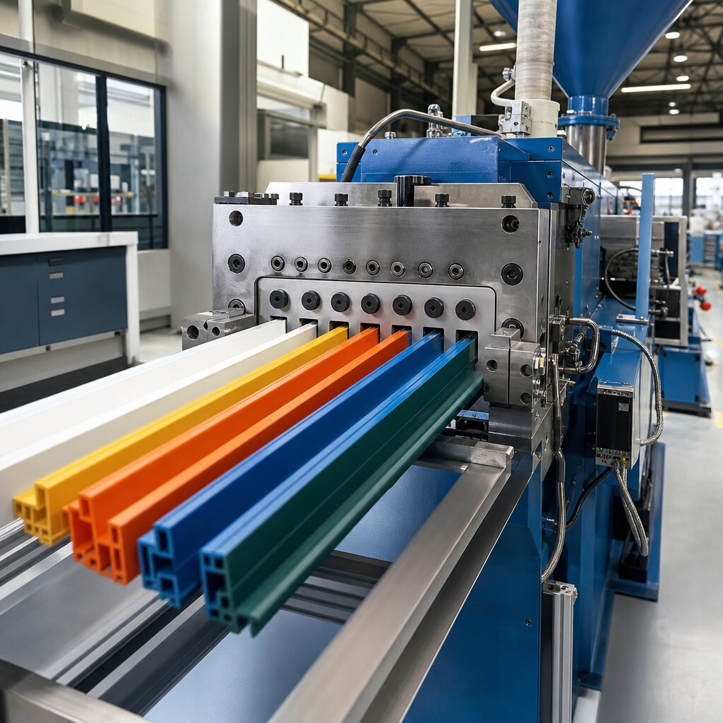
Extruded profiles are not machined parts. They are formed, hot, moving, and they cool while being pulled, sized, and cut. So tolerances are real, yes. But they are also… a little more alive than people expect.
This article is basically a reality check. Not in a pessimistic way. More like, here’s what is actually reasonable, what drives variation, and how to design a profile that comes out consistent run after run.
Extrusion tolerance is not one number
A profile print usually has a mix of features, and each one behaves differently in the line.
So instead of asking “What tolerance can you hold?” the better question is:
“What tolerance can you hold on this feature, in this material, at this size, with this tooling approach, at this output rate?”
That sounds like a lot. It is. But it is also why good extruders will ask follow up questions before they throw a number at you.
What’s actually moving around during extrusion
A quick mental model helps.
Plastic leaves the die hot. Then it is cooled and pulled to size. During that whole trip:
- The melt temperature shifts a bit.
- The puller speed shifts a bit.
- Vacuum or calibration conditions shift a bit.
- Material lot, moisture, fillers, and regrind percentage can shift a bit.
- The profile shrinks as it cools, and shrink is not perfectly uniform.
Even if every setting is “locked,” the process is still physical. It breathes. And thin legs, wide flats, and asymmetrical shapes feel that breathing more than chunky, balanced shapes.
Typical tolerance ranges people can live with
There is no universal table that covers every custom profile. Still, in day to day custom extrusion, a few patterns show up a lot:
- Overall width and height can often be held fairly consistently, especially when the profile is sized well and the design is stable.
- Wall thickness tends to vary more than people expect, particularly on thin sections.
- Small details like barbs, snap features, and knife edges can be sensitive to temperature and wear, so they need extra attention in design and inspection planning.
- Straightness and twist are their own category. You can have a profile that is “in spec” dimensionally but still has a little corkscrew to it if the geometry and cooling are fighting each other.
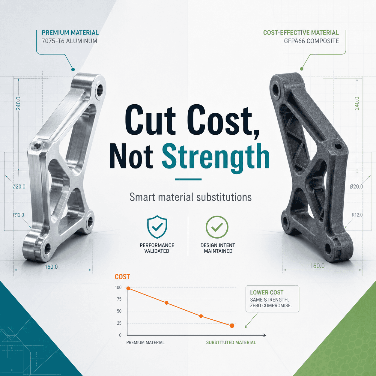
If you need extremely tight tolerances across many features at once, it is not impossible, but it usually means tradeoffs. Slower line speeds, more process control, more frequent checks, potentially different material, sometimes even secondary operations.
The biggest drivers of tolerance, in plain terms
1. Profile geometry, especially thin vs thick areas
Uneven wall thickness is the quiet troublemaker. When one section cools faster than another, shrink becomes uneven. That leads to bowing, curl, and dimensions that drift depending on how the part is supported and measured.
If you can, design for more uniform wall sections. Not always possible, I know. But when it is possible, it pays back immediately.
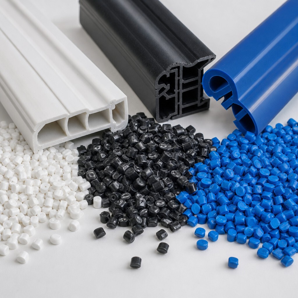
2. Material choice (and its behavior)
PVC, HDPE, ABS, TPE, polypropylene, filled compounds, flame retardant grades. They all cool differently and shrink differently. Some are forgiving. Some are not.
Also, softer materials can be harder to measure consistently because they deform slightly under calipers or fixture pressure. That turns into arguments that are really just measurement method issues.
3. Tooling design and calibration strategy
Die design matters. So does downstream sizing. Some profiles want a calibration plate, some want vacuum calibration, some want more support, some want less restriction to avoid drag marks.
Tooling can also wear. You might start a run holding a tight detail, then over time that edge rounds off. Good shops plan for that.
4. Puller speed and cooling balance
Higher output is great. But chasing speed can widen variation. Cooling too aggressively can lock in stress or distort thin legs. Cooling too softly can cause sag.
Getting this balance right is where experience shows up.
Measurement is half the tolerance conversation
This part gets weirdly overlooked.
Two people can measure the same profile and get different numbers because:
- They are measuring at different points along the length.
- One is measuring right after extrusion and one after full cooling.
- One is using calipers on a soft part and compressing it.
- One is using an optical comparator and the other is not.
- One is holding the part flat and the other is letting it relax naturally.
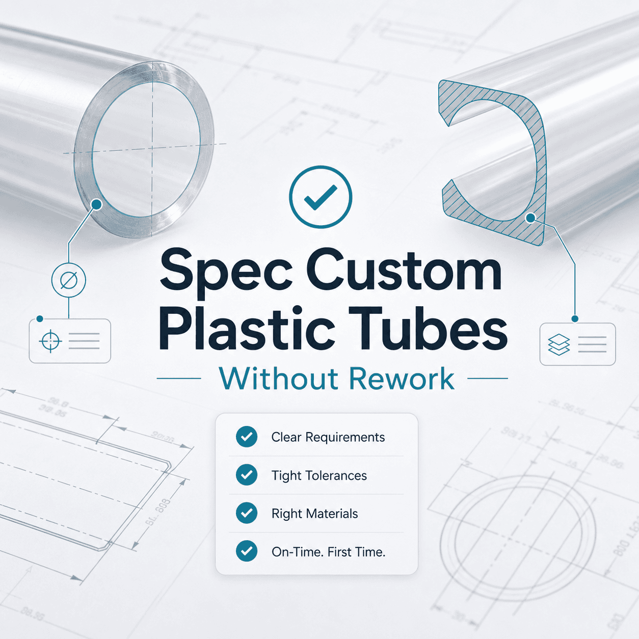
If your tolerance is tight, define the inspection method on the print or at least in the quality plan. Where to measure, how long after extrusion, what fixture (if any), and what tool.
That alone can prevent the classic “it’s out of spec” email chain.
So what’s realistic, in one sentence?
Realistic tolerances in extruded profiles are the result of geometry, material, tooling, and measurement method working together. If one of those is fighting the others, the tolerance you want might be technically possible but commercially painful.
If you are in the quoting or redesign stage and want a straight answer on what’s reasonable for your specific profile, it is usually fastest to share the drawing and highlight the truly critical features. Accord Plastics Corp does custom plastic extrusion with made to spec profiles and tubing, plus tooling support and inline process monitoring, so you can have that tolerance conversation early, when it is still easy to adjust the design. You can start here: https://accordplastics.com.
FAQs (Frequently Asked Questions)
Why can’t plastic extrusion tolerances be treated like machined part tolerances?
Plastic extruded profiles are formed hot, moving, and cooling during production, unlike machined parts which are cut from solid materials. This dynamic process means tolerances are influenced by factors like temperature shifts, puller speed variations, and material behavior, making them more variable and ‘alive’ than typical machined part tolerances.
What factors influence tolerance variations in plastic extrusion?
Tolerance variations arise from several sources including melt temperature fluctuations, puller speed changes, vacuum or calibration shifts, material properties (lot, moisture content, fillers), shrinkage during cooling which is not uniform, and the geometry of the profile such as thin legs or asymmetrical shapes that react differently during processing.
How do profile geometry and wall thickness affect extrusion tolerances?
Uneven wall thickness causes uneven cooling and shrinkage rates across the profile, leading to bowing, curling, and dimensional drift. Thin sections tend to vary more than thick ones. Designing for uniform wall thickness helps minimize these issues and results in more consistent dimensions run after run.
What role does tooling design play in maintaining extrusion tolerances?
Tooling design including die shape and downstream sizing methods (vacuum calibration vs calibration plates) directly affects how well features hold their dimensions. Tool wear over time can degrade detail sharpness. Proper tooling design combined with regular calibration and maintenance is crucial for consistent tolerance control.