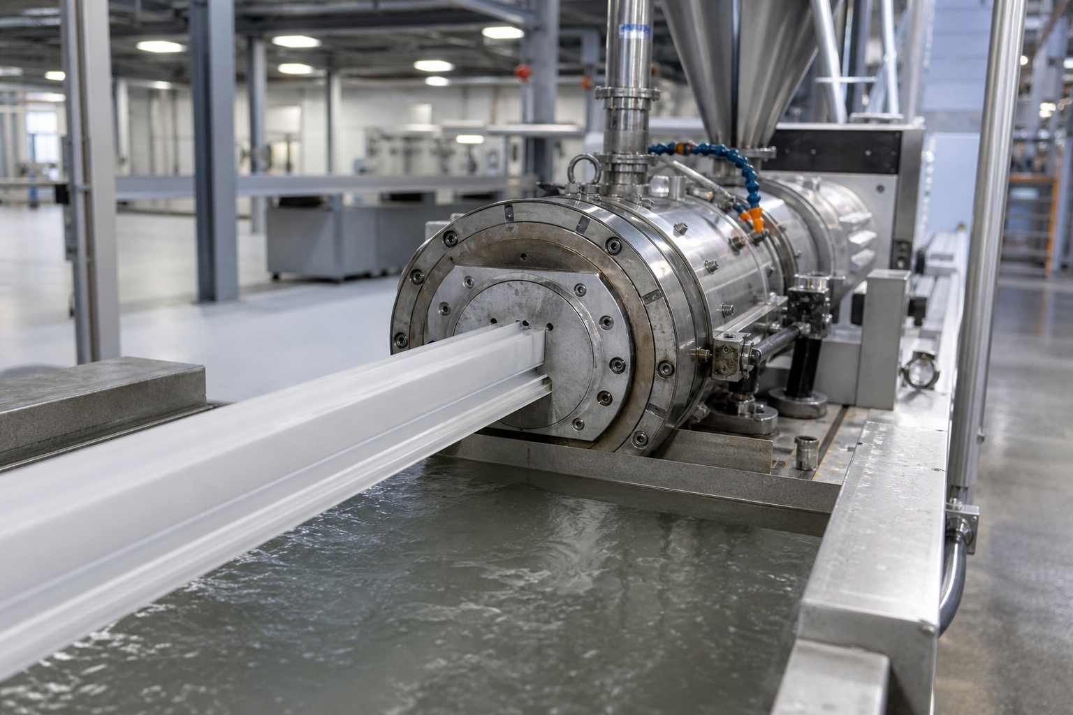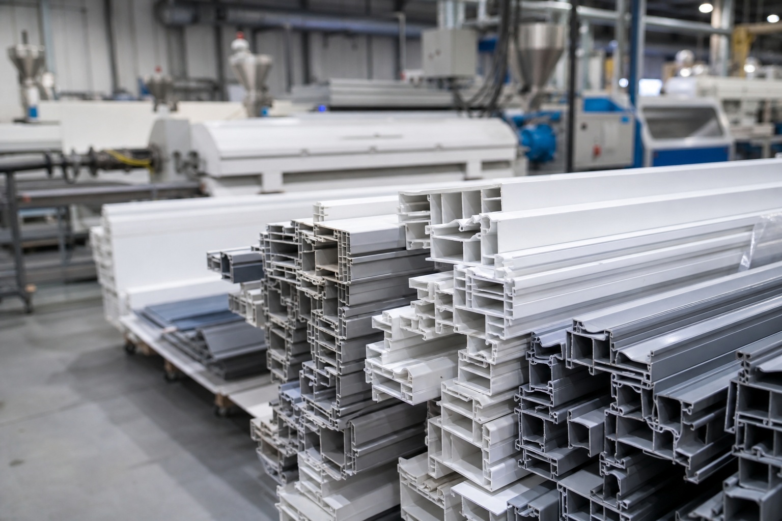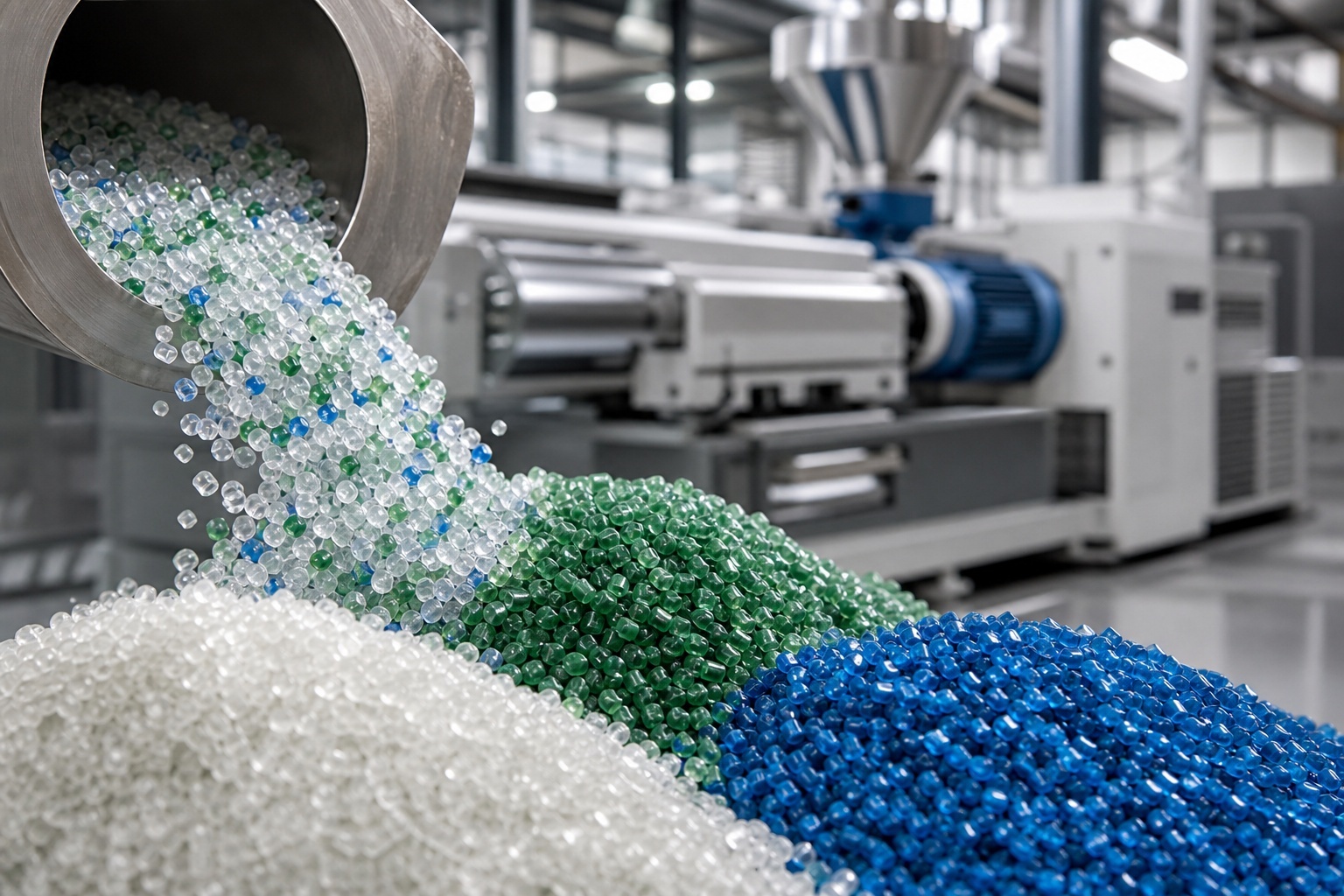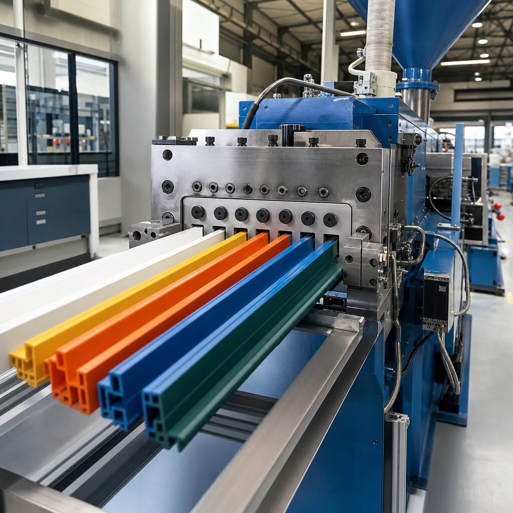
A tolerance that looks ordinary on a machined-part drawing can be difficult—or needlessly expensive—on a continuous plastic profile. Extrusion involves hot polymer flowing through a die, cooling, shrinking and being pulled at line speed. Every part of that system affects the final cross-section.
The best time to discuss plastic extrusion tolerances is before the drawing is released for tooling. When the extruder understands which dimensions drive fit, sealing or assembly, the die, calibration method, material and inspection plan can be designed around function instead of a blanket set of tight limits.
Extrusion Tolerances Are Not Moulding Tolerances
Injection moulding fills a closed, temperature-controlled cavity. Extrusion continuously forms a profile through an open die and then controls it during cooling. The process is highly repeatable, but it behaves differently.
An extruded profile can change with melt temperature, pressure, puller speed, cooling rate, residual stress and material lot. Complex hollow shapes may distort as they cool. Long pieces introduce bow, twist and straightness considerations that do not appear in a short moulded component.
The die opening is therefore not a one-to-one copy of the final part. Toolmakers compensate for swell, drawdown, cooling and unequal flow. The complete custom extrusion process shows how design review, tooling, trial runs and quality control turn a drawing into a production profile.
What Counts as a “Standard” or “Tight” Tolerance?
There is no universal tolerance that applies to every polymer, feature and supplier. Capability depends on nominal size, wall thickness, cross-sectional complexity, material, equipment, measurement method and required length. Industry-standard profile tolerances are often discussed in a broad range around ±0.1 mm to ±0.3 mm for suitable dimensions, but that is context—not permission to apply ±0.1 mm to the entire drawing.
As an early design conversation, dimensions may be grouped like this:
- Ordinary profile dimensions: moderate limits that suit stable materials and accessible features.
- Tight functional dimensions: selected widths, gaps, wall sections or interfaces controlled with enhanced calibration and process monitoring.
- Geometric requirements: straightness, bow, twist, flatness and angularity specified over a defined length.
- Post-processed features: holes, notches or end cuts held separately from the continuously extruded cross-section.
Ask the manufacturer for part-specific capability. A tolerance should reflect the exact feature and inspection condition, not a generic marketing claim.
How Material Changes Dimensional Stability
Rigid PVC
Rigid PVC is widely used because it processes predictably and can offer good dimensional control, clean corners and stiffness. Compound formulation, impact modifiers, filler and processing history still matter. Flexible PVC introduces more movement, and durometer should be treated as part of the specification.
ABS
ABS offers toughness, appearance and machinability, with useful dimensional stability for many profiles. Grade selection, cooling and unsupported geometry affect results. Outdoor applications typically need a UV strategy such as a cap layer or appropriate formulation.
HDPE and Other Polyolefins
HDPE and polypropylene provide chemical resistance, toughness and low density, but their higher shrinkage and thermal movement may make tight dimensional control more challenging. Flexible walls and long lengths require realistic straightness expectations.
Flexible TPE/TPV
Soft seals and gaskets are measured differently from rigid channels. The force applied by calipers can compress a feature and change the reading. Durometer, recovery, conditioning and a defined measurement fixture become critical.
Accord’s PVC vs ABS vs PP material selector outlines practical trade-offs in stiffness, impact, chemical exposure, UV and dimensional behaviour. If HDPE is being considered, discuss it explicitly with the engineering team rather than treating all polyolefins as interchangeable.
Geometry Factors That Affect Tolerance
Profile design and material cannot be separated. The following features commonly increase variation or tooling effort:
- abrupt transitions between thick and thin walls;
- unbalanced material mass across the section;
- deep channels and unsupported legs;
- thin webs beside heavy bosses;
- sharp internal corners;
- large hollow chambers;
- long, flat surfaces that can bow; and
- multiple materials in a co-extrusion.
Uniform wall thickness and balanced geometry help the profile cool evenly. Radii improve flow and reduce stress concentration. Where function allows, locating features and datum surfaces can be designed to make measurement and assembly more reliable.
Straightness must always include a gauge length. “1 mm straightness” is incomplete: over 100 mm, one metre or the full cut length? The answer changes both feasibility and cost.
Process Factors Behind Dimensional Variation
During a run, output is influenced by resin moisture and lot, melt temperature, screw speed, head pressure, tooling temperature, vacuum calibration, cooling-water conditions, haul-off speed and line stability. Ambient conditions and cut handling can matter too.
Vacuum calibrators and sizing fixtures support tight profiles during the critical cooling stage. In-line measurement and statistical process control help detect drift before it becomes scrap. A first-article report confirms the initial setup, while production sampling verifies the ongoing process.
Measurement conditions must be agreed. A warm profile measured immediately after the line may not match a conditioned part at standard room temperature. Long flexible lengths can also take the shape of their packaging. Define conditioning time, sample support, instrument, measurement force and location for critical characteristics.
How to Specify an Extrusion on a Drawing
1. Identify the Functional Interfaces
Start with how the profile works. Which surface locates the part? Which gap accepts another component? Which lip seals? Which wall takes a screw? Mark these as critical-to-function and explain the mating condition.
2. Use a Clear Datum Scheme
Choose stable, accessible datum features that reflect assembly. Avoid dimension chains that accumulate unnecessary variation. Baseline or coordinate dimensions can make relationships easier to control and inspect.
3. Apply Tolerances Selectively
Use general tolerances for non-critical features and tighter values only where functional analysis supports them. Bilateral limits are not automatically better than profile, position or fit-based controls. Discuss geometric dimensioning with the extruder before release.
4. Define Material Completely
Specify resin family and grade or required performance, colour, durometer where applicable, recycled-content restrictions, UV or flame requirements and approved alternatives. Different compounds shrink and flow differently.
5. State Length and Secondary Operations
Define cut-length tolerance, end condition, hole and notch locations, protective film, packaging and whether dimensions apply before or after fabrication. Secondary machining may economically hold a feature that is impractical to control continuously.
6. Define Inspection and Acceptance
State the measurement method for soft or complex features, inspection frequency, conditioning and any capability requirement. If you need first-article inspection, PPAP or material certificates, include them at the quoting stage.
Prototyping Before Production Tooling
A prototype should answer risk questions, not merely resemble the part. Additive or machined samples can validate envelope, interfaces and assembly, but they do not reproduce extrusion flow, shrinkage, surface finish or long-length behaviour.
The production-intent trial is where the extruder tunes the die and calibrator, measures the profile and identifies adjustments. Budget for iteration. For a complex section, expecting the first trial to produce every dimension at nominal is less realistic than planning a controlled tool-correction cycle.
Share mating parts, samples and functional context whenever possible. A supplier can often suggest a more tolerant interface that preserves performance and reduces tooling risk. Accord’s custom profile manufacturing capabilities describe a six-step path from definition and design through trial and production.
Why Tighter Tolerances Cost More
Tolerance affects more than inspection. Tight limits may require more sophisticated tooling, vacuum calibration, slower line speeds, additional trial and correction loops, more frequent sampling, special gauges, tighter raw-material control and higher scrap allowances.
The lowest-cost drawing is not the loosest one. It is the drawing that is tight where failure matters and flexible everywhere else. Over-tolerancing cosmetic or non-mating dimensions increases cost without improving the product. Under-tolerancing a sealing gap or snap interface creates assembly failure and field risk.
Ask for a tolerance-and-cost review before approving tooling. Moving one non-critical dimension from a tight custom limit to a proven process range may pay for better control of the feature that actually drives performance.
Frequently Asked Questions
Can every dimension be held to ±0.1 mm?
Usually not economically, and sometimes not physically, across a complex profile. Capability must be reviewed by feature, material, size, tooling and measurement method.
Does a softer material need a wider tolerance?
Often, but the larger issue is defining how it is measured. A fixture or optical method may be needed to avoid compressing the part.
How should bow and twist be specified?
State the maximum deviation over a defined supported length, plus the conditioning and measurement setup. Avoid an undefined “must be straight” note.
Can machining solve a tight-tolerance feature?
Yes, for some holes, notches, cut lengths and local interfaces. The manufacturer can compare the cost of secondary machining with tighter continuous-process control.
What should be sent for a quote?
Provide a dimensioned drawing, material and performance requirements, annual volume, cut lengths, colour and finish, mating information, inspection needs and timeline. Highlight critical characteristics.
Get a Manufacturable Tolerance Review
Plastic extrusion tolerances are a design decision, a tooling decision and a quality decision at the same time. Involving the extruder early helps protect fit and function while avoiding cost that does not add value.
Accord Plastics builds custom dies and vacuum calibrators in-house and works with rigid and flexible materials, co-extrusions, hollow profiles and secondary finishing. Request a custom extrusion quote and include your drawing, material, volume and critical dimensions for a practical review before prototyping.